How to Run Diagnostics on an E‑Scooter Controller: Step‑by‑Step DIY Troubleshooting and Testing Guide
Introduction
Running diagnostics on an e‑scooter controller is essential for maintaining peak performance and preventing unexpected failures. This guide will teach the reader how to identify common faults, test voltage and signal integrity, and verify protective functions. By following the systematic approach, one can extend the lifespan of the scooter and reduce costly repairs. The information presented is valuable for hobbyists, repair technicians, and owners who prefer a hands‑on solution.
What You’ll Need
- Multimeter with DC voltage and continuity functions
- Insulated screw‑driver set
- Heat‑shrink tubing or electrical tape
- Safety gloves and goggles
- KH866 High Power E‑Bike Motor Controller – useful as a replacement or test unit
- Ezweiji 36V/48V E‑Bike Motor Controller – ideal for low‑power diagnostic setups
Step 1: Safety Preparation and Power Isolation
Before any testing begins, disconnect the scooter battery and remove the key to eliminate stored energy. Wear insulated gloves and safety goggles to protect against accidental short circuits. Verify that the controller is not receiving any voltage by measuring the input terminals with a multimeter set to DC voltage. This precaution prevents damage to testing equipment and ensures personal safety throughout the diagnostic process.
Step 2: Visual Inspection of the Controller
Examine the controller housing for signs of overheating, corrosion, or loose connectors. Look for burnt components, discolored solder joints, or broken wires, which often indicate internal failures. If the controller is the KH866 High Power E‑Bike Motor Controller, its aluminum alloy case should be intact with no dents that could impair heat dissipation. Document any anomalies with photographs before proceeding to electrical testing.
Step 3: Verify Wiring Connections and Continuity
Using the multimeter’s continuity setting, check each labeled wire on the controller for proper connection to the motor, throttle, and battery leads. The KH866 controller features clearly labeled wires, which simplifies identification and reduces wiring errors. Ensure that the ground (GND) wire shows low resistance to the chassis, confirming a solid earth path. Replace any frayed or damaged wires with heat‑shrink tubing to maintain insulation integrity.
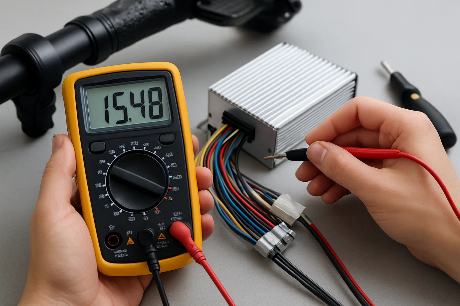
Step 4: Measure Battery Input Voltage
Reconnect the battery temporarily and measure the voltage at the controller’s input terminals. For a 48 V system, the reading should be close to 48 V with a tolerance of ±0.5 V; higher voltages may indicate over‑charging, while lower values suggest a depleted battery. The Ezweiji 36V/48V E‑Bike Motor Controller includes an LCD panel that displays real‑time voltage, making this step quicker for low‑power setups. Record the measurement for reference when comparing against manufacturer specifications.
Step 5: Test Hall Sensor Signals (If Applicable)
If the scooter uses a hall‑sensor motor, verify that the controller correctly detects the sensor signals. Set the multimeter to DC voltage and probe each hall sensor wire while manually rotating the motor shaft; a stable 5 V signal should appear when the sensor is active. The KH866 controller automatically switches between hall and sensor‑less modes, so a missing signal may trigger the fallback mode, resulting in reduced performance. Confirm that the controller’s mode indicator (if present) reflects the correct operating mode.
Step 6: Evaluate PWM Output to the Motor
Pulse‑width modulation (PWM) controls motor speed; an oscilloscope or a multimeter with PWM capability can display the duty cycle. With the throttle at half‑position, the PWM duty cycle should be approximately 50 % of the maximum value. The Ezweiji controller’s sine‑wave technology provides smoother PWM transitions, which can be observed as a cleaner waveform on the scope. Any irregularities, such as spikes or low duty cycles, may point to a faulty controller or throttle sensor.
Step 7: Check Braking and Regeneration Functions
Engage the scooter’s brake lever while the motor is running and monitor the voltage drop across the motor terminals. A rapid decrease indicates effective regenerative braking; a sluggish response suggests a problem with the controller’s braking algorithm. The KH866 controller offers responsive braking without a reverse function, making it suitable for steep climbs where precise deceleration is required. Verify that the controller does not cut power abruptly, which could damage the battery.
Step 8: Perform Load Test Under Real‑World Conditions
After confirming static measurements, conduct a short ride on a safe, flat surface while observing controller temperature and performance. Use the LCD panel on the Ezweiji controller to monitor real‑time mileage and battery health during the test. The aluminum alloy housing of both controllers provides excellent heat dissipation, but prolonged high‑load operation should not raise the surface temperature above 70 °C. If overheating occurs, consider adding a supplemental fan or improving airflow around the controller.
Step 9: Diagnose Protective Circuit Activation
Many controllers incorporate under‑voltage, over‑current, and thermal protection mechanisms. Simulate an over‑current condition by briefly applying a higher load than the rated 1500 W (for the KH866) and observe whether the controller shuts down safely. The Ezweiji controller’s built‑in protection will cut power and display an error code on its LCD, preventing battery damage. Document any protection triggers, as they often reveal underlying issues such as shorted motor windings or battery imbalance.
Step 10: Final Documentation and Decision Making
Compile all measurements, observations, and photographs into a diagnostic report. Compare the recorded values with the specifications provided by the manufacturer; deviations beyond tolerances typically warrant component replacement. If the controller fails multiple tests, the KH866 High Power E‑Bike Motor Controller is an affordable universal replacement at $41.99 with a 3.8/5 rating from 14 reviews. For lower‑power scooters, the Ezweiji 36V/48V E‑Bike Motor Controller offers a budget‑friendly option at $38.99 and a 4.2/5 rating from 33 reviews.
Tips & Pro Tips
- Always calibrate the multimeter before use to ensure accurate voltage readings.
- When testing hall sensors, rotate the motor slowly to avoid damaging the sensor magnets.
- Use heat‑shrink tubing on all exposed connections to prevent moisture ingress, especially in rainy climates.
- Keep a spare set of labeled wires; mislabeled connections are a common source of intermittent faults.
- For persistent overheating, install a small 12 V fan powered from the controller’s auxiliary output.
Troubleshooting Common Problems
| Symptom | Possible Cause | Solution |
|---|---|---|
| No power to motor | Battery disconnected or controller input fuse blown | Reconnect battery securely; replace fuse if burnt. |
| Intermittent speed changes | Loose throttle wire or faulty hall sensor | Inspect and reseat throttle connector; test hall sensor continuity. |
| Excessive noise | Controller operating in non‑hall mode with poor PWM | Switch to a compatible hall‑sensor motor or use a controller with smoother sine‑wave output such as the Ezweiji model. |
| Controller shuts down under load | Over‑current protection triggered | Check for shorted motor windings; verify battery health. |
Conclusion
This guide has outlined a comprehensive approach to diagnosing e‑scooter controllers, from safety preparation to detailed electrical testing. By following each step, one can accurately identify faults, verify protective functions, and decide whether repair or replacement is necessary. The recommended controllers provide reliable performance and serve as excellent spare parts for both high‑power and low‑power scooters. Armed with this knowledge, the reader can maintain a safe, efficient, and longer‑lasting e‑scooter.
Products Mentioned in This Guide
Frequently Asked Questions
What tools are required to run diagnostics on an e‑scooter controller?
You need a multimeter (DC voltage and continuity), insulated screwdrivers, heat‑shrink tubing or electrical tape, and safety gloves and goggles.
How can I check the controller's voltage output safely?
Set the multimeter to DC voltage, connect the probes to the controller’s power terminals, and compare the reading to the scooter’s rated voltage.
What does a continuity test reveal about the controller?
A continuity test identifies broken wires, shorted phases, or open circuits within the controller’s internal connections.
How do I verify that the controller’s protective functions are working?
Trigger a fault condition (e.g., short the throttle input) and confirm the controller cuts power or signals an error on the display.
When should I replace the controller instead of repairing it?
Replace the controller if voltage readings are consistently out of spec, continuity tests show multiple open circuits, or protective functions fail repeatedly.